Friday, December 12, 2008
final review: becker/turkula


from orifice to monster security:
jon turkula/john becker fa2008
Our project has gone down two major paths. One: interactive aperture that helps define the relation between desirable objects, people and places. this mode of investigation sought to create a physical relationship between the two spaces, such as user/ storage. The second seemingly tangential trajectory we took was the interface between two very separate groups. We chose to look at the security of a a bank vault. On fifth avenue in midtown, chase bank has an all glass facade between the public on the street and the bank vault. This shift in the idea of security was pivotal in this, the new information age. No longer guarded by a stone wall, but by glass. This project is sited to be along this glass wall as a beautiful, historical look at the relation between the public and the most sacred. Small mouth open as if to guard the space, following the pedestrians along the street. The interface allows for distant observation to be unencumbered, while when the wall is approached a warning is made.
Labels: aperature, awesome, becker, distance, monster, ping sensor, relays, turkula
Final Prototype 03
Final Prototype 02
here, we test the prototype with the FSR sensors -- one touch on the "positive" side controls one group of flexinol (keeping it open), another touch adds a second group, and a third controls all. one touch on the "negative" side wrests control of one group from the positive (keeps it closed). and so on..
Labels: touch
Final Prototype 01
here, we're testing the default state, prior to user engagement. Ambient information (in this case, small movement and hints of opening) acts to pique the curiosity of passersby and encourage them to band together to monitor what is beyond.
Labels: touch
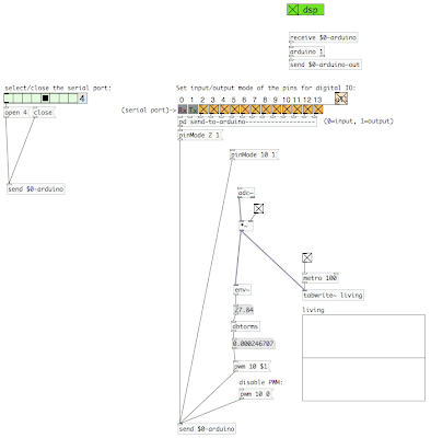
urban sound monitor 2 from lleigha on Vimeo.
Labels: arduino, audio, booth, pd, puredata, sound, urban


Labels: arduino, audio, booth, pd, puredata, sound, urban
Labels: arduino, audio, booth, flexinol, led, pd, puredata, sound
sound input with flexinol and led output

Labels: arduino, audio, booth, flexinol, led, pd, puredata, pwm, sound
Tile movement sequence as train approaches the 116th ST subway station
1.digital input
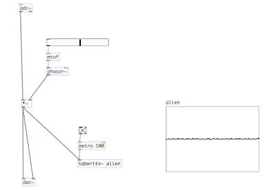
2.analog/sound input
3.train at 103rd ST. heading North
4.train at 110th ST. heading North
5.train at 125th ST. heading SouthLabels: Sound TIles
tile movement diagram

Beating Facade-Final

final prototype

2nd prototype
1st prototype
Group-Guillermo, Heejoo, Sang Wan, Adolfo
prototype II - two cells
prototype I - one cell
Tuesday, December 9, 2008
prototype - sound input
prototype - digital input
Prototypes 7,8
Labels: touch
Sunday, November 23, 2008
sound experiments
Labels: ambient, arduino, audio, booth, flexinol, pd, puredata, sound, urban
Tuesday, November 11, 2008
mid rev.

codes_111108

midterm_111108


prototype
In order to maximize the movement, two batteries and longer flexinol wire are used.

Group-Guillermo, Heejoo, Dae Wook, Sang Wan, Adolfo
sound as analog input_111108


Prototype 6


Monday, November 10, 2008
Prototype1 (basic frame of interactive advertisement wall)
We tested different length of flexinol wire to maximize movement of output.

Group-Guillermo, Heejoo, Derik, Sang Wan, Adolfo
Sunday, November 9, 2008
audio input and flexinol output
Labels: arduino, audio, booth, flexinol, pd, puredata, sound
flexinol and pure data toggle


Labels: arduino, booth, flexinol, pd, puredata, relay, toggle
Tuesday, November 4, 2008
audio input and pwm led output
Labels: arduino, booth, led, microphone, pd, puredata, pwm
led pulse width modulation with pure data


Labels: arduino, booth, led, pd, pulsewidthmodulator, puredata, pwm
Sunday, November 2, 2008
mic-in/arduino-out with pure data

Labels: arduino, booth, microphone, pd, puredata
audio input with laptop microphone and pure data
Labels: audio, booth, microphone, pd, puredata, sound
led pulse with pure data

Labels: arduino, booth, led, pd, pulse, puredata
led toggle with pure data

Labels: arduino, booth, led, pd, puredata, toggle
LED patterns with ARDUINO
Labels: arduino, array, booth, led
Tuesday, October 28, 2008
Touch Sensor Prototype 5: LED + Flexinol
TriggerPin0 PIN 5 ' Pin that gets the touch sensor input
TriggerCount VAR Byte
LOW 11
LOW 15
TriggerCount = 0 IF TriggerPin0 = 1 THEN
TriggerCount = TriggerCount + 1 ' Check pin0, add to counter
DEBUG "sensor 0 on", CR
ENDIF
IF TriggerPin1 = 1 THEN
TriggerCount = TriggerCount + 1 ' Check pin0, add to counter
DEBUG "sensor 1 on", CR
ENDIF
IF TriggerCount >= 2 THEN ' Both on, turn on flexinol
HIGH 15
DEBUG "both sensors on", CR
PAUSE 1000
ELSEIF TriggerCount = 1 THEN ' Otherwise, turn on LED
HIGH 11
DEBUG "one sensor on", CR
ENDIF
PAUSE 1000
LOOP
Labels: flexinol, piezo, touch
two sensors and multiple output

Tuesday, October 21, 2008
Buying more flexinol locally
These guys are in Staten Island and can get any length of flexinol wire quite quickly.
What we started off with was the .006 'HT' (high temperature) wire.
The flexinol only needs 1.5V, and they recommend a more controlled source than battery power (we used an AC-DC converter from RadioShack, which works like a charger cable/power source for any electronic device.. it regulates the power much better than a battery).
two LED & flexinol with two PIR sensor


'{$STAMP BS2}'
'{$PBASIC 2.5}'
PIR PIN 0
PIR2 PIN 15
counter VAR Byte
Main:
'DO
IF PIR = 1 THEN
IF PIR2 = 1 THEN
counter = counter +1
HIGH 6
HIGH 8
DEBUG HOME, "TRIPPED...", DEC3 counter
DO : LOOP UNTIL PIR = 0
DEBUG HOME, "CLEARED...", DEC3 counter
DEBUG HOME, "TRIPPED2...", DEC3 counter
DO : LOOP UNTIL PIR2 = 0
DEBUG HOME, "CLEARED2...", DEC3 counter
LOW 6
LOW 8
'PAUSE 100
ENDIF
ENDIF
IF PIR2 = 1 THEN
IF PIR = 1 THEN
counter = counter +1
HIGH 6
HIGH 8
DEBUG HOME, "TRIPPED...", DEC3 counter
DO : LOOP UNTIL PIR = 0
DEBUG HOME, "CLEARED...", DEC3 counter
DEBUG HOME, "TRIPPED2...", DEC3 counter
DO : LOOP UNTIL PIR2 = 0
DEBUG HOME, "CLEARED2...", DEC3 counter
LOW 6
LOW 8
'PAUSE 100
ENDIFENDIF
'{$PBASIC 2.5}'
PIR PIN 0
PIR2 PIN 15
counter VAR Byte
Main:
DO
IF PIR = 1 THEN
counter = counter + 1
HIGH 2
HIGH 6
DEBUG HOME, "TRIPPED...", DEC3 counter
DO : LOOP UNTIL PIR = 0
DEBUG HOME, "CLEARED...", DEC3 counter
LOW 2
LOW 6
PAUSE 100
ENDIF
IF PIR2 = 1 THEN
counter = counter +1
HIGH 8
DEBUG HOME, "TRIPPED2...", DEC3 counter
DO : LOOP UNTIL PIR2 = 0
DEBUG HOME, "CLEARED2...", DEC3 counter
LOW 8
ENDIF
PAUSE 100
LOOP
'{$STAMP BS2}'
'{$PBASIC 2.5}'
PIR PIN 0
PIR2 PIN 15
counter VAR Byte
Main:
'DO
IF PIR = 1 THEN
HIGH 2
HIGH 6
DEBUG HOME, "TRIPPED...", DEC3 counter
DO : LOOP UNTIL PIR = 0
DEBUG HOME, "CLEARED...", DEC3 counter
IF PIR2 = 1 THEN
counter = counter +1
HIGH 8
DEBUG HOME, "TRIPPED2...", DEC3 counter
DO : LOOP UNTIL PIR2 = 0
DEBUG HOME, "CLEARED2...", DEC3 counter
LOW 2
LOW 6
LOW 8
'PAUSE 100
ENDIF
ENDIF
IF PIR2 = 1 THEN
HIGH 8
DEBUG HOME, "TRIPPED2...", DEC3 counter
DO : LOOP UNTIL PIR2 = 0
DEBUG HOME, "CLEARED2...", DEC3 counter
IF PIR = 1 THEN
counter = counter +1
HIGH 2
HIGH 6
DEBUG HOME, "TRIPPED...", DEC3 counter
DO : LOOP UNTIL PIR = 0
DEBUG HOME, "CLEARED...", DEC3 counter
LOW 2
LOW 6
LOW 8
'PAUSE 100
ENDIF
ENDIF
Touch Sensor Prototype 4
In this prototype we tested a thicker Flexinol wire (.015 HT) and an AC adapter.

Labels: flexinol, piezo, touch
Here is the flexinol wire paired with the LED showing two separate responses to motion at different distances.
this is a test to show that the led sytem we developed previously can be used with the flexinol wire...
' PingTest.bs2
' {$STAMP BS2}
' {$PBASIC 2.5}
time VAR Word
DO
PULSOUT 15, 5
PULSIN 15, 1, time
time = time ** 2251 DEBUG CR, "Distance = ", DEC4 time, " cm"
PAUSE 20
IF time < 0015 THEN HIGH 2
PAUSE 10
IF time = 0015 THEN LOW 2
PAUSE 10
IF time > 0015 THEN LOW 2
PAUSE 10
LOOP
Monday, October 20, 2008
test relay


Testing Relay to amplify output to make bigger movement of flexinol wire.
It was still making small movement.
10/13/08
Group-Guillermo, Heejoo, Derik, Sang Wan, Adolfo
LED with PIR sensor
Instead of using flexinol wire for output , we tested LED sensor to check if PIR sensor is working properly.
experimenting two LED with two PIR sensor. It was working properly, but two system can't operate together due to code.
10/06/08
Group-Guillermo, Heejoo, Derik, Sang Wan, Adolfo
PIR Sensor


Statement


Saturday, October 18, 2008
Arduino+Amplifier+MAX/MSP (Sound as an Input )


We used the same amplifier setup as the previous exercise, this time we added MAX/MSP to visually represent the sound input.
Group - Sang Hwan Park, James O'Meara, Nita Yuvaboon, Ki Ung Na, Yemeze Edozie
Labels: Sound TIles
LED fader with MAX/MSP
Labels: Sound TIles
Physical Pixel Controller
Group - Sang Hwan Park, James O'Meara, Nita Yuvaboon, Ki Ung Na, Yemeze Edozie
Labels: Sound TIles
Tuesday, October 14, 2008
Touch Sensor Prototype 3: Relay

We experimented with a relay to get more power directly to the Flexinol. The Flexinol was unable to take the extra voltage. It produced smoke and quick abrupt movements. We will experiment with a thicker or longer Flexinol wire for our next prototype which will be able to withstand more voltage and will produce greater movement.
Labels: flexinol, piezo, relay, touch
Two LEDs with PING sensor
We decided to see if we could produce some variability in the output. to test this we set up one led to be triggered at any distance less than 15cm, and another led to be triggered at less than 3o cm. It worked so well, that we think other people should read this and tell us about how impressed they are. We are looking to use this type of output to create an output that has some gradation of effect based on distance.
' PingTest.bs2
' {$STAMP BS2}
' {$PBASIC 2.5}
time VAR Word
DO
PULSOUT 15, 5
PULSIN 15, 1, time
time = time ** 2251
DEBUG CR, "Distance = ", DEC4 time, " cm"
PAUSE 20
IF time <>
IF time = 0015 THEN LOW 0
IF time > 0015 THEN LOW 0
IF time <>
IF time = 0030 THEN HIGH 3
IF time > 0030 THEN LOW 3
LOOP
1 led and PING sensor
This was an excersize in getting the PING sensor to activate a LED when the distance recorded is less than 15 cm.
' PingTest.bs2
' {$STAMP BS2}' {$PBASIC 2.5}
time VAR Word
DO
PULSOUT 15, 5
PULSIN 15, 1, time
time = time ** 2251
DEBUG CR, "Distance = ", DEC4 time, " cm"
PAUSE 20
IF time <>
IF time = 0015 THEN LOW 0
IF time > 0015 THEN LOW 0
LOOP
measuring distance with PING sensor

' PingTest.bs2
' {$STAMP BS2}' {$PBASIC 2.5}
time VAR Word
DO
PULSOUT 15, 5
PULSIN 15, 1, time
time = time ** 2251
DEBUG CR, "Distance = ", DEC4 time, " cm"
PAUSE 100
LOOP
Sunday, October 12, 2008
arduino + speaker + sound recognition


using ardurino with speaker to recognize the different sound frequency and display them on both ardurino and prossesing screen.
Group - Sang Hwan Park, James O'Meara, Nita Yuvaboon, Ki Ung Na, Yemeze Edozie
Labels: Sound TIles
arduino + Piezo + melody output
using ardurino connected with Piezo to play melody.
Group - Sang Hwan Park, James O'Meara, Nita Yuvaboon, Ki Ung Na, Yemeze Edozie
Labels: Sound TIles
arduino + Piezo + 'knock' + light output

using ardurino connected with Piezo to recognize simple 'knock' sound and LED light output.
Group - Sang Hwan Park, James O'Meara, Nita Yuvaboon, Ki Ung Na, Yemeze Edozie
Labels: Sound TIles
arduino + light output
Group - Sang Hwan Park, James O'Meara, Nita Yuvaboon, Ki Ung Na, Yemeze Edozie
Labels: Sound TIles
Tuesday, October 7, 2008
LED patterns with ARDUINO
Below is our first code, and video of prototype.
int ledPin = 13; // LED connected to digital pin 13void setup(){ pinMode(ledPin, OUTPUT); // sets the digital pin as output}void loop(){ digitalWrite(ledPin, HIGH); // sets the LED on delay(1000); // waits for a second digitalWrite(ledPin, LOW); // sets the LED off delay(1000); // waits for a second}

Our second prototype utilized a bread board in conjunction with the arduino diecimila in order to control patterning among a group of four LEDs.
int timer = 100; // The higher the number, the slower the timing.int pins[] = { 2, 3, 4, 5 }; // an array of pin numbersint num_pins = 4; // the number of pins (i.e. the length of the array)void setup(){ int i; for (i = 0; i < i =" 0;" i =" num_pins">= 0; i--) { digitalWrite(pins[i], HIGH); delay(timer); digitalWrite(pins[i], LOW); }}

![]()